SYSCON-RKC offers a wide range of high performance temperature and process controllers.
We have developed the following chapter to assist you in understanding the control theories of SYSCON RKC-instruments and help you select the most appropriate instrument for your application.
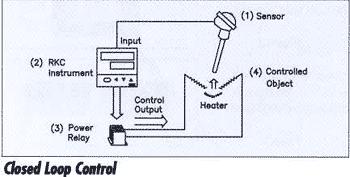
CLOSED LOOP CONTROL
The closed loop temperature control system is actually a form of feedback control. The loop consists of four
components:
1. The sensor – i.e., thermocouple, sensitive temperature detector (RTD) or thermistor
2. SYSCON-RKC temperature controller
3. The power device – i.e., magnetic relay, solid state relay (SSR), mercury contactor, silicon controlled
rectifier (SCR) or a valve
4. The controlled object – i.e., electric heating element, flame control valve or other load
To obtain accurate control of your process loop, it is necessary to properly match the characteristics of all
four components. The temperature of the controlled object is detected by a sensor and converted into an
electric signal. The electric signal is fed into the SYSCON-RKC controller and compared with the set point as a feedback value. If any deviation exists, the process variable is calculated from the deviation and the power device delivers the appropriate corrective power to the controlled object. The closed loop process is the most precise form of temperature control. Temperature is the most frequently controlled process variable, however, SYSCON-RKC instruments also control many other process variables such as pressure, flow, and level.
CONTROL ACTION
Control action is classified into three types: ON/OFF, Proportional and PID. Each action has unique characteristics which will meet specific requirements for different applications.
ON/OFF CONTROL
ON/OFF control is the simplest and least expensive form of control. The output signal from the control is either full-ON or full-OFF depending on the direction of the deviation from set point. ON/OFF action takes place if any deviation occurs. This action has a quick response but it is sensitive to input noise that causes
chattering (ON/OFF switching in short intervals). Therefore, in actual use, the ON/OFF action has some
hysteresis referred to as dead ban or control sensitivity.
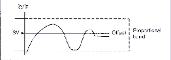
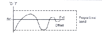
PROPORTIONAL ACTION
Proportional Action is referred to as (P) or gain. With proportional action, the controlled object no longer
switches as a direct result of the set value (SV). The SYSCON-RKC instrument compares the difference between the set value and the process variable and controls the output proportional to the deviation. This proportional action is active within a user-definable zone around the set point called the proportional band (P). When the temperature rises into the proportional band, the output becomes gradually smaller and the temperature stabilizes somewhere within the proportional band. Proper adjustment of the proportional band will result in smooth control. However, it is seldom that the actual temperature stabilizes exactly on the set point. It usually stabilizes with some deviation called offset. SYSCON-RKC instruments have an adjustable proportional band to meet your process requirements.
INTEGRAL ACTION
The degree of integral action referred to as (1) or reset is expressed as integral time in seconds. The purpose of the integral action is to automatically compensate for any steady state offset inherent with a proportional controller. The integral action moves or resets the proportional band up or down depending on the offset. The integral time on SYSCON-RKC instruments is adjustable and determines how fast the proportional band is moved.
DERIVATIVE ACTION
The degree of derivative action, referred to as (D) or rate, is expressed by derivative time. With SYSCON-RKC controllers, this action is adjustable in seconds. The controller measures the rate of the temperature increase and moves the proportional band to minimize overshoot. The change in the output is directly proportional to therate of change in the process value (PV).
ANTI-RESET WINDUP
The anti-rest windup (ARW) inhibits the integral action until the PV is within the proportional band thus reducing overshoot on start-up. ARW inhibits the integral action by preventing the controller from moving the proportional band during start-up. This action is measured in a percentage of the proportional band and can be set from 0-100% on SYSCON-RKC Instruments.
DIRECT / REVERSE ACTION
Direct action is the control method used for cooling or chilling applications. The output of the controller increases with respect to an increase in the measured value; this relationship is direct. Reverse action is the control method used for heating applications. The output of the controller decreases with respect to an increase in the measured value, consequently producing reverse action.
HEAT / COOL CONTROL
Heat/cool control provides heating and cooling action in one controller. This is particularly effective when both heating and cooling control is required in extruder barrel temperature control.
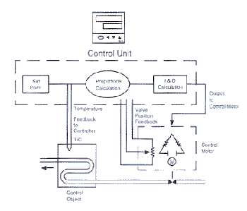
POSITION PROPORTIONAL ACTION
Position proportional action is used to control flow rate by using a control motor. The position of the control
motor valve and the subsequent temperatures are transmitted to the controller. In the control process, a delay in the control valve could cause the temperature to oscillate. The use of a control motor with a potentiometer improves system response because the valve position is transmitted by the resistance of a potentiometer. Typically, this value is a 135 OHMS resistance slide wire feedback. The control motor has two directions of movement. OPEN and CLOSED. A signal is produced to drive the motor either OPEN or CLOSED. As a result, there is a zone called deadband to prevent both opening and closing outputs from being ON at the same time.
OPERATION MODES
AUTO MODE – Automatic operation performs closed loop control with values established via the front keypad of the instrument or through digital communications.
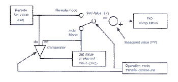
REMOTE MODE – Automatic output operation performs control with the set value established through an external analog signal.
MANUAL MODE – Manual operation adjusts the control output to a selected level independent of the sensor input (open loop).
BALANCELESS / BUMPLESS, REMOTE / AUTO TRANSFER
Some controlled objects cannot withstand rapid output changes that result when switching from remote to auto mode or vice versa. The balanceless / bumpless, remote/auto transfer function produces a smoother transfer byrestricting rapid change in output or set value during transfer.
ANALOG RETRANSMISSION OUTPUT
The analog retransmission output feature of SYSCON-RKC instruments permits the process engineer to retransmit either the process variable, the set value, the control output or the remote set value to an external device. Common uses for this signal are chart recorders, dataloggers, PLC’s and distributed control systems.
DATA COMMUNICATION
Data communication refers to parallel and serial communications as differentiated from analog communications.
PARALLEL COMMUNICATION
Parallel communication refers to data bits that are transmitted in parallel format with separate lines for each bit through simple interface circuitry.
SERIAL COMMUNICATION
Serial communication refers to data bits that are transmitted sequentially through a single line. For longer cable lengths, serial communication is less expensive than parallel communication.
RS-232C
The RS-232C standard is the most widely used interface for serial data communications as defined by the Electronics Industries Association (EIA). RS-232C is used for interfaces between data terminal equipment and data communication equipment. Data rated range from 50 to 19200 baud and the maximum permissible line length under the RS-232C specification is approximately 15 meters.
RS-422A
The RS-422A standard specifies a low impedance differential signal enabling the line length to reach approximately 1200 meters.
RS-485
The RS-485 standard specifies the electrical characteristics of the driver and the receiver to be used by the line interface. It does not specify or recommend any protocol; the protocol is left to the user. This communications standard is used where a balanced transmission line is required in party-line configuration. The EIA RS-485 standard is widely accepted because it enables users to configure inexpensive local area networks and multi-drop communication
links using twisted pair wire and the protocol of their choice. The user has flexibility in matching cable quality, signaling rate and distance to the specific application to optimize cost versus performance.
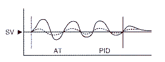
AUTOTUNING
Implementing proper PID values can often be difficult and time-consuming. With the autotuning function, PID
values are automatically measured, computed and optimum PID constants are set. The purpose of deriving accurate PID values is to achieve stable control. The autotuning feature of the instrument is activated during temperature rise and/or when control is stabilized from any process state. The PID parameters are derived via the software of the microprocessor in the controller. The instrument actually goes into ON/OFF control for two or three cycles. The microprocessor calculates the amplitude of the slope of the rise and fall of the process over time and automatically establishes the PID values. This allows the process engineer to tune precise PID loops.
ENHANCED AUTOTUNING
As a pioneer on PID autotuning, STSCON-RKC offers autotuning on all our microprocessor-based instruments. Traditional autotuning algorithms use a limit-cycle method which requires cycling at the set point in order to obtain optimum PID parameters. This method is widely used throughout industry but some overshoot still exists. When the autotuning button is pressed, PID constants are calculated during the three cycles of ON/OFF control. Even though the control produces very good results, it is not acceptable in all applications. SYSCON-RKC has developed a new PID autotuning method using a new PID algorithm called enhanced autotuning or Enhanced AT. The basic concept of this method is summarized in the Autotuning Bias diagram. Enhanced autotunig is available on the F,G and FAREX_SR MINI Series.
ENHANCED AUTOTUNING CYCLES
With enhanced autotuning, you can select two or three ON/OFF cycles. When autotuning needs to be completed as soon as possible, two-cycle autotuning should be used. Three-cycle autotuning is recommended when information is required for PID calculation.
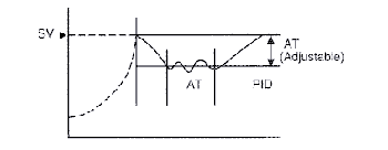
AUTOTUNING BIAS
Early autotuning methods required ON/OFF cycles at set point, which resulted in a large overshoot. With the new feature of AT Bias, autotuning can be initiated below set point. Depending on the characteristics of the process, the bias range can be adjusted to suppress overshoot. Even if autotuning is started at the set point, it continuesbelow the set point (at the preset value). When autotuning is completed, temperature returns to the original set point.
OUTPUT LIMITER
With early autotuning methods, an instrument was either 100% (ON) or (OFF) and large overshoot often occurred. With SYSCON-RKC’s output limiter, this overshoot can be reduced. If during ON/OFF cycles, the output limiter’s high setting is 80% and low is 20%, the output is 80% at ON and 20% at OFF. The result is a decrease in the size of ON/OFF waves. If the output range is narrowed further, the ON/OFF waves become smaller which minimizes the effects on the process.
ALARMS
The alarm function activates the alarm lamp (Red) and relay to produce the alarm status if the deviation or measured value (PV) reaches the alarm set value. Alarm functions are most applicable when a danger signal must be created for the safety of personnel or equipment.
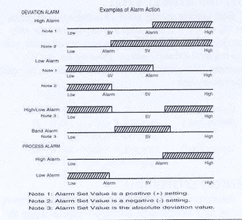
DEVIATION/PROCESS ALARMS
1. Deviation Alarm
The alarm function is activated if the measured value (PV) reaches a preset deviation from set value (SV). Therefore, the deviation alarm value moves with a set value (SV) change.
a. High Alarm
The alarm function is activated if the deviation measured value (PV) exceeds the alarm set value (SV) to produce the alarm status.
b. Low Alarm
The alarm function is activated if the deviation measured value (PV) falls below the alarm set value (SV) to produce the alarm status.
c. High/Low Alarm
The alarm function is activated if the deviation measured value (PV) is less than or greater than the alarm set value (SV) to produce the alarm status.
d. Band Alarm
The alarm function is activated if the deviation measured value (PV) is within the alarm set value (SV) to produce the alarm status.
2. Process Alarm
This alarm function is activated if measured value (PV) reaches the alarm set value. The process alarm is an absolute value that is separate from the set value (SV). Regardless of set point change, this value will remain constant.
HOLD ACTION
The alarm hold action permits the process engineer to configure the alarm to be masked or suppressed upon start-up.
ALARM DELAY TIMER (Time Delay Relay)
The alarm delay timer function is used to delay the alarm action. If the alarm state is released during this delay period, the alarm output will not be activated. External disturbances such as noise, may cause a momentary increase of a process value into the alarm area. The alarm delay function prevents alarm output in these cases.
ALARM ENERGIZED / DE-ENERGIZED
Energized relay contact is closed under the alarm status.
De-energized relay contact opens under the alarm status.
HEATER BREAK ALARM
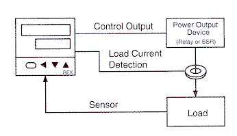
Heater Break Alarm (HBA) supplies an instrument with a current transformer which digitally displays the currentdraw. When the control output is ON and the load current drops below a specified minimum, an alarm is triggeredindicating that a heater has failed. When the control output is OFF and the heater current is still present, the HBA is used to signal a welded relay contact. Early detection of a broken heater of relay can limit costly damage to machinery and materials. Generally, the HBA is set to approximate 85% of the load current. Using a 20 Amp heateras an example, the HBA would be set at 85% or 17 Amps. If the current fails to reach 17 Amps with the output relay closed, the HBA will indicate that the heater is not functioning correctly.
HBA and SYSCON-RKC INSTRUMENTS
The HBA is an option on S,C,D,F and FAREX-SR MINI systems. The HBA is also available as a separate unit that can be added to existing control systems. The stand-alone HBA unit includes a module and an external current transformer. The compact HBA-21 is designed for single phase wiring applications. The HBA-T20 is designed for use in single phase, either zero cross or phase angle SCR control applications. The HBA-T30 is designed for use in three phase, either zero cross or phase angle SCR control applications.
Each instrument that incorporates an HBA, can compare input versus set point, can make power calculations and can produce an output signal to the load in a form appropriate to each power output device. A closed loop in conjunction with the load and sensor is created. The HBA then detects faults in the load or power output device and causes an alarm output.
HBA’S EARLY ERROR DETECTION
Since the HBA functions as a control loop sentry, it detects problems long before costly damage to machines and materials occurs. Many times, a conventional alarm detects problems well after damage takes place. With the HBA, the problem can be rectified before and damage occurs, saving not only time but money.
HBA’S FUNCTIONS
The heater break alarms are relay contact outputs which can be set to drive remote lights and buzzers that provide a visual or audible warning when a particular heater is functioning incorrectly.
Other uses for Heater Break Alarms are:
1. The HBA initiates an alarm when the control output is ON and the heater current is below the set value of HBA.
2. HBA signals that there is a welded relay contact when the control output if OFF and there is heater current.
3. Heater amperage can be shown digitally on the controller’s front panel.
4. HBA is available as a stand-alone module to retrofit existing controllers.
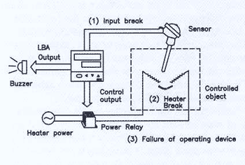
Protection from Control Loop Breaks (Loop Break Alarm)
In the past, control manufacturers have offered protection for broken thermocouples by adding a high impedance turn-off signal to the signal from the thermocouple. Thermocouples are very low impedance devices and as long as the thermocouple was functioning, it shorted out the high impedance turn-off signal. If the thermocouple failed to open, break protection signal would then set output power to zero. Although thermocouples are the most likely control element to fail, c complete temperature control loop has several hundred elements such a integrated circuits, resistors, connections, etc., that may also fail. A failure in any one of these can cause the out-put to go full-ON or full-OFF and overheat the process. On the other hand, if full-OFF occurs, the process will be underheated. Loop Break Alarm solves these problems by monitoring almost every part of the entire control loop.
SETTING MEMORY AREAS
Eight separate memory areas are available to store groups of PD values. The parameters that can be stored are main set point, proportional band, integral time, derivative time, control response and alarm settings. When the set point is changed, other parameters can be easily modified by changing the memory area.
Example:
Memory Area 1 SV = 50%, P=10%, 1 = 240, D = 60,
Slow, A1 = 5%, A2 = 5%
Memory Area 2 SV = 80%, P = 20%, 1 = 360, D = 90,
Slow, A1 = 10%, A2 = 20%
REMOTE SETTING (RS)
With the remote setting function, the set point of the instrument can be set or changed by the external DC current or voltage signal. The instrument controls the object to maintain this set value. The external setting signal must be applied constantly.
1. RS Digital Filter This is a first order lag filter whose function is achieved by software provided for rejecting noise contained in remote set value (RS).
2. RS Ratio
This is the function of inputting the remote set value (RS) obtained by multiplying the remote set value (RS) by a multiplying factor. (Remote set value (RS) X (RS ratio) = Remote set value (RS) used for the display and control.
SETTING CHANGE RATE LIMIT (RAMP)
This is the function of setting amount of set value (SV) change per unit time when the set value (SV) is changed.
Application example of setting change rate limits:
-When rapid set value (SV) change needs to be avoided.
-When simplified program control needs to be performed in combination of memory area with setting change rate limit.
CLASSIC PID
Classic PID control is widely used for stable control results that can be obtained by setting constants of P (proportional band), I (integral time) and D (derivative time).
PID control, with one-degree-of-freedom, is not a perfect control method. If PID constants are set to obtain better characteristics against set point changes on start-up, it becomes more sensitive to external disturbances. On the contrary, if PID constants are set to obtain better characteristics against external disturbances, it is typical that characteristics against set point are reduced. In a normal temperature control application, this compromise has been ignored to some extent.
Advanced process control requirements mandate tighter control. To obtain better characteristics against both external disturbances and set point changes with a conventional control, two types of PID constants are required. The control must change from one type to the other as soon as the control state has been changed. In this method, one set of PID constants is set to obtain better characteristics against external disturbances and other PID constants (a, b, y) are set to obtain better characteristics against set point. If we have properly selected constants of P, I, D, a, b, y, matched for applications, we have a control with quick stabilization against external disturbances and good response to set point changes.
It is difficult to set proper P, I and D constants even with conventional PID; if additional constants like a, b and y are used, this control method is no longer practical.
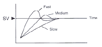
SYSCON-RKC offers three types of user-defined responses for start-up of set point change: FAST, MEDIUM and SLOW. Consequently, the user can choose the amount of overshoot required for various applications. If no overshoot is desired, select the SLOW response to reach the desired set point.
BRILLIANT PID
SYSCON-RKC has enhanced traditional pid control and it is called Brilliant PID with two-degrees-of-freedom. Traditional PID calculation is a PV-Derivative algorithm with one-degree-of-freedom. Brilliant PID utilizes an enhanced I-PD algorithm with two-degrees-of-freedom which allows for optimum response to operation upsets by selection of the FAST, MEDIUM of SLOW response to match the process during start-up or set point changes. If a fast response is required, FAST is selected. If overshoot is critical, SLOW is chosen.
Depending upon the type of response selected, Brilliant PID chooses which algorithm to use. The relationship between these two methods is shown in the following table:
Response I-PD PV-Derivative PID
SLOW 100% 0%
MEDIUM 50% 50%
FAST 0% 100%
I-PD’s characteristics suppress large output changes caused by set point change. A SLOW response uses I-PD action to produce a smooth set point change and this action takes longer than the PV-Derivative type of control. On the contrary, when the FAST response is selected, PV-derivative PID is used. Subsequently, a faster response is obtained, although output change is greater than I-PD due to P action. When MEDIUM response is selected, both actions are used equally. Brilliant PID is achieved with SYSCON-RKC’s new Enhanced autotuning feature. Enhanced autotuning selects optimum PID parameters for the best response to external disturbances or process upsets. Depending upon the requirements, a FAST, MEDIUM or SLOW setting must be selected manually to respond to a set point change.
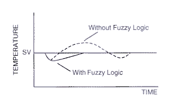
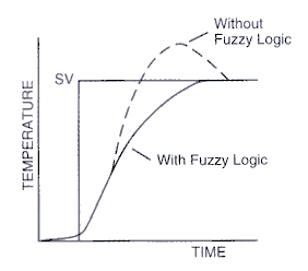
FUZZY LOGIC
Fuzzy logic is the latest development in machine intelligence that enables computers and controllers to determine a wider range of responses. Computers and controllers manipulate precise facts that have been reduced to strings of zeros and ones or statements that are either true or false, they do not have the reasoning capability of the human mind. Controllers with fuzzy logic emulate human beings by assisting the instrument to determine responses between two values. This technology allows the temperature controller to function like an expert operator.
Fuzzy logic technology is particularly effective:
– In suppressing overshoot
– In shortening start-up time
– In suppressing process upsets when frequent load changes occur
– In suppressing upsets that occur with set point changes